
Thermal Products Inc Optimizes Heat Exchanger Process and Cost Effectiveness for Each Heat Exchanger Application
Process applications involving heat transfer can take optimal advantage of design nuances to achieve the right balance of suitability for the duty and cost effectiveness. Many times, the fluid properties in terms of corrosiveness, volatility, the presence of solids and fouling properties predetermine the type of exchanger specified within a given process. Other considerations such as accessibility for cleaning, footprint, temperature approach or capital cost dictates the final specification. At some point, the design engineer must strike a balance between the subjective and objective, between the optimal in process and the cost of construction and ease of maintenance.
Look first at the process, then at the heat exchanger
Suitability for the application must first be determined by asking the right questions. While not a simple process, as such an analysis is often laden with potential trade-offs, this exercise will effectively eliminate some designs that fail to meet the base demands of the application that cannot be compromised. Only after the operational and process considerations are clearly understood can one begin to narrow in on an appropriate heat exchanger specification. A full-service heat exchanger manufacturer should be expected to provide both thermal and mechanical design, assuring that the finished product takes operational requirements into account. Some manufactures employ sophisticated thermal modeling software that can accurately predict heat release curves and multi-phase performance. Full service manufacturers offer thermal performance guarantees.
Some of the questions answered during the evaluation are:
• Is this application one that cannot tolerate interstream or cross contamination leakage?
• Are either of the fluids toxic, corrosive or lethal if exposed to the atmosphere?
• Are there operational advantages in achieving low approach temperatures?
• Does the process lend itself to heat recovery? Is there a high value attached to this?
• Is this a batch operation? What is the cost benefit from rapid batch cycling?
• Do either of the fluids contain solids and what size?
• What is the maximum temperature or pressure that either stream could reach in operation?
• Are there fluctuations in the flows or temperatures that could result in thermal expansion?
• Are either of the fluids high fouling, requiring frequent service of the exchanger?
• Are there space limitations that cannot be avoided without high construction cost?
• Is sufficient plant cooling water available? Is cooling with air an option?
Fluid Property Considerations – Critical Fluids
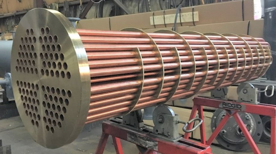
• Critical fluids such as corrosive, expensive or lethal fluids should be positively contained. TEMA Type BEM, AEM and NEN are welded and have no gaskets or packing inside the shell. The tube side can be cleaned mechanically, but the shell side must be cleaned chemically as the bundle is fixed. Avoid the use of internally or externally packed floating head designs for volatile or toxic shell side fluids.
• In sanitary, lethal or explosive applications, it is common to place the critical fluid inside the tubes, regardless of other considerations. In such cases shell and tube exchangers are typically specified with high-alloy materials and/or 3a polished surface finish. Mechanical and electropolish techniques are acceptable. Exchangers can be manufactured with clad tube sheets in large diameters and solid in smaller diameters.
• To reduce tube to tube sheet joint failures, specify that the tube sheet holes be reamed and polished to prevent any material presence during the tube expanding operation.
• In lethal service, specify strength welding, not seal welding of the tube joint. A proper strength weld is not a surface weld, but adds material where the tube end is set slightly in from the tube sheet surface. It is designed to withstand the full operating pressure without expanding the tube. Light expanding is typically performed only to prevent liquid from entering the crevice formed between the tube OD and tube sheet.
• An outside packed floating head exchanger is designed so that only the shell side fluid is exposed to the packing, allowing critical, toxic or volatile fluids to pass though the tube side.
• In plate heat exchangers, semi-welded designs eliminate 90% of the required gasket area on the critical side and therefore provides a measure of containment of one of the circuits while allowing the other to be opened for periodic maintenance.
• Fully welded plate heat exchangers should be specified for lethal, penetrating or critical fluid applications or where gasket material contact is not acceptable. Fully welded plate exchangers are often specified for ammonia evaporation due to the high performance and containment characteristics.
Fluid Property Considerations – Fluids with Solids
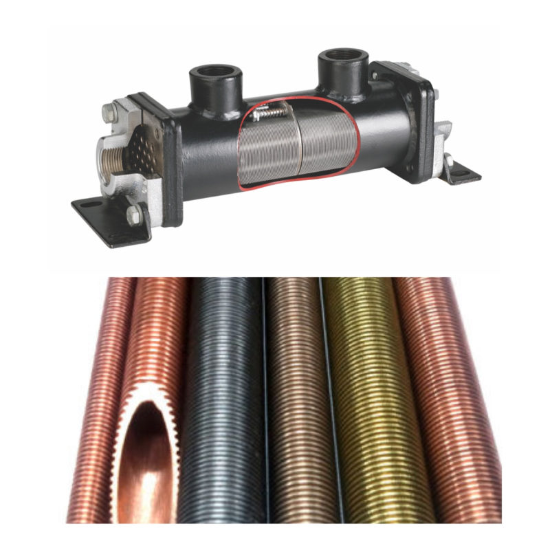
• Shell and tube exchangers can be specified with larger flow passages to accommodate a certain amount of solids or particulate without fouling or clogging.
• Plate exchangers can be specified with flow passages having wide annular spaces and minimal contact points instead of the common herringbone or chevron pattern. This design allows passing of slurries or fluid with solids and fibers, typically at the expense of operating pressure.
• When cooling high volumes of gas, enhanced high-fin tubing or plate fin bundles increase the heat transfer coefficient in the shell side while maintaining a low pressure loss. Plate-fin bundles provide superior thermal performance due to the increased effective surface and provide longer service life due to the continual tube support throughout the bundle. Divided-flow TEMA “J” shells can also be used to accommodate gas streams in the shell.
Viscous Fluids
• It is typical to place the viscous fluid in the shell circuit of a shell and tube where it is easier to enhance the heat transfer coefficient by manipulating the fluid velocity. Viscous fluids tend to enter laminar flow more readily when placed in the tube side, but is often necessary to achieve very low pressure loss requirements.
Pressure and Temperature
• In applications with thermal expansion or contraction, specify a u-tube or floating tube sheet design.
• It is customary to place high temperature liquids on the shell side to eliminate the presence of gaskets or packing.
• Depending on the fluid viscosity, to achieve low pressure drop for a process fluid, place the flow inside the tube circuit.
• For cooling gas, to achieve low pressure drop, specify a plate fin tube bundle instead of traditional bare or enhanced tube surfaces.
Temperature Approach and Crossing
• It is economically viable to achieve an approach temperature of no less than 10°F in counter-current flow, single pass shell and tube heat exchangers.
• To achieve closer approach performance, or some amount of temperature crossing, a plate exchanger should be specified.
Sanitary Designs for Fine Chemicals, Foods and Pharmaceuticals
• Double tube sheet designs prevent interstream or cross contamination leakage if there is a failure of the inner tube to tube sheet joint. Joint failure results in shell side fluid leaking to atmosphere. A retaining collar can be installed to collect any fluid from the failed joint.
• Double wall shell and tube and plate designs are available for the prevention of interstream contamination. Although there is metal to metal contact, some loss of thermal conductivity should be expected.
• Sanitary designs for plate exchangers include polished plates and sanitary fluid ports. Plate designs allow rapid disassembly to expose both process streams for mechanical cleaning, but it is customary to provide Clean-In-Place systems in such applications.
Cleanability and Service
• Generally, place corrosive or high fouling fluids through the tube circuit with straight tube designs to facilitate mechanical cleaning. Non-fouling fluids can be processed through the tube circuits of u-tube designs.
• Shell and tube exchangers can be manufactured with “A” type heads where the tube side ports are radial and the cover plate is bolted to the channel with heavy-duty hinges. This allows quick access to the tube side without disturbing any connective piping. Because of the “A” heads, tube cleaning can also be accomplished in TEMA type AEW designs without disturbing any connective piping.
• It is easier to detect tube leaks on the tube side of shell and tube exchangers. Rupture disks are typically placed on the shell side to indicate a pressure change that can be indicative of a tube failure.
• For applications where complete drainability for service or process fluid changes is required, place the critical fluid in the tube circuit. Shell side drainability can be enhanced by the use of drain plugs between notched baffles. Drainage is typically enhanced by purging the shell with compressed air. In some cases, the exchanger can be mounted at a 3-5° slope to facilitate tube side draining.
• Tube side drainability of multi-pass heads can be accomplished by installing a drain plug that straddles the vertical pass rib inside the head, allowing access to both hemispheres. Sanitary units demand self-drainability without removing the heads.
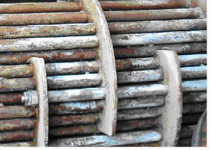
• For applications requiring shell side access for mechanical cleaning, avoid exchangers with both tube sheets welded to the shell because only chemical cleaning is possible. Instead specify one of the removable bundle designs with a square tube pitch to allow brushing between tube rows.
• For plate and frame models, glueless, snap-in or clip-on gasketed plates can be cleaned or regasketed without removing the plate from the frame, however for high-fouling duties, where the plate pack must be opened frequently for cleaning, the glued gasket may reduce overall service costs.
Equipment Cost
• Use the entire available pressure drop to maximize the fluid velocity and thereby the heat transfer rate.
• Specify commercial standard designs where applicable. Apply ASME U or UM Stamp for applications or insurance regulations that require code inspection.
• Specify TEMA Type BEM, AEM and NEN when other considerations are met. This straight tube, all welded design is the least complex and costly and provides the maximum tube count for a given shell diameter. Type NEN exchangers have the shell and the head welded directly to the tube sheet and are the lowest cost.
• There is a hybrid TEMA type design available that features a removable bundle but uses O-rings to seal the floating end. This reduces the unit cost provided the O-ring elastomer is compatible with the shell side process fluid, operating pressure and temperature.
• An externally sealed floating head exchanger is less costly than the full internal floating head design, but both the tube side and shell side fluids must be non-volatile and non-toxic.
• In shell and tube exchangers undergoing thermal expansion and contraction, the lowest cost selection is a U-tube design, but mechanical cleanability of the u-bends is difficult and individual tube replacement is not possible for inner tubes. The next step in terms of cost is the TEMA type AES, which has a full tube count, but requires more labor to pull the tube bundle for service. The highest cost alternative is the TEMA type AET, which sacrifices some tube surface to allow room for the internal floating head, but is easier to service.
• Placing high-pressure gas or liquids on the tube side can reduce cost by eliminating the need for a heavy wall shell to retain the operating pressure.
• Apply fouling factors to thermal calculations judiciously as small factor increases result in large effective surface requirements.
The Bottom Line
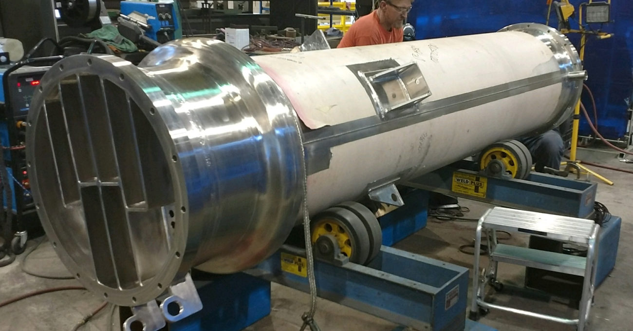
Once these operational considerations have been addressed and understood, Thermal Products Inc can better focus on the actual exchanger specification. There are three classes of shell and tube exchangers available. The lowest cost option is to select a commercial standard design. Many are available off-the-shelf or very quickly as the engineering and components are standardized. Many are available to 12” in diameter and in a variety of materials and Code options. A few manufacturers offer modified designs that are standardized to 42” in diameter at lower cost than traditional TEMA equipment. For more demanding requirements, specify one of the TEMA designs. These are typically available through 60” in diameter. Beyond these are fully customized heat exchangers that tightly incorporate sophisticated thermal and mechanical modeling to provide a “solution” approach.
Shell and Tube versus Plate Technology
One of the fundamental choices involves the use of shell and tube versus plate technology. While this is an involved subject, some basic differentiations are readily available.
• Plate exchangers can be gasketed, welded, semi-welded or brazed. Each has its own advantages and limitations.
• Plate materials include stainless steel, Titanium, Titanium-Palladium, SMO-254, Incolloy, Nickel, Hastelloy, Monel, Inconel and Tantalum.
• Gasketed plate exchangers allow users to open and clean both fluid surfaces. Semi-welded models allow cleaning of one of the fluids. Welded and brazed exchangers are full contained and can only be chemically cleaned.
• Plate exchangers have flow characteristics that cause high fluid turbulence at lower fluid velocities, breaking up the boundary layer and effecting very high heat transfer rates.
• Gasketed plate exchangers are limited to around 300 psi at 450°F. Gaskets are available for compatibility with virtually any process fluid, but engineered resin gaskets can significantly add to the cost of the exchanger.
• The flow channels between plates can be narrow with many contact points to increase thermal efficiency, or wide with few or no contact points to facilitate the passing of solids of fibers.
• As plate packs can be expanded, a designer can anticipate future process requirements and incorporate an upgrade path as conditions change. Because fluid velocity decreases as plates are added in parallel, some loss in the overall heat transfer rate can be expected to occur, so future expansion needs should account for this factor.
For applications cooling compressed gas, or for operating at high pressure or temperature, or where reduced maintenance costs associated with gaskets is desired, for many industrial duties, shell and tube technology is still the best direction.
With heat removal requirements, and the emphasis on close control and recovery of heat energy in chemical processing installations, it is prudent for a plant designer to establish ongoing relationships with experts in the discipline. Ideally, one should have the ability to objectively evaluate the differences between given shell and tube options and even between shell and tube and plate alternatives. Seeking a manufacturer that offers all of the options available enhances this objectivity that can equate to the best solution being applied to the requirement.
With API Heat Transfer